So I made myself a mechanical keyboard

To clarify:
- I designed a keyboard layout similar to the standard Apple keyboard (with some notable deviations);
- Using Fusion360 from some hand-drawn sketches, modeled a three-piece case complete with milling/routing instructions to CNC-machine each piece from solid blocks of aluminum;
- designed and sent for manufacturing a custom Printed Circuit Board (PCB) and sourced the Bill-of-Material (BOM);
- wrote a keymap file and some custom functions in C using the most-excellent QMK, an open-source keyboard firmware; and
- assembled the thing (with minor incident).
Quite a few people have asked me about it, so I thought to write out a Build Log. Intended audiences are people who:
- are curious how one would build a keyboard from (nearly) scratch,
- would like to do this themselves and want high-level guidance,
- need to convince themselves that they should instead commission a bespoke keyboard,
- like to nerd out about mechanical keyboards and small batch manufacturing, and/or
- are happy to placate their friend and his ridiculous machinations.
To that end, the following is a high-level overview of what goes into producing a keyboard from scratch and the work and decision-making that goes into such an endeavor. For the non-keyboard enthusiasts among my readership, I’ll briefly introduce terms with some cursory information (indented). This will occasionally get technical; but, instead of rushing headlong into minutiae, links will direct you to someone who is either more qualified (or more interested/thorough) on the details.
To that end, this is the level of content I would have liked to have read when I first ventured out to build a consumer-grade custom keyboard. There’s not much guidance for intrepid souls who seek to produce something that could be mistaken for a high-end consumer product and not (with much respect) builds that are clearly kits, prefabbed parts, home-built, or frankensteined together. Indeed, it was those types of builds that opened me up to the possibility.
In short, I wanted something that worked for me and that I could have convincingly bought at my local CompUSA.
In what follows, I’ll go through the why, the what, and the how to what I have dubbed the K73 because, well, that’s how many keys it has and I have no plans to market it. If you want to see final result photos, feel free to scroll until you get the visuals.
I won’t mind if you skim the prose. It’s your time. Do what you’d like.

Cool story. But why?
Probably like you, I spend my days ramming ideas and code through an Apple-blessed keyboard connected to some way station of a computer before it ambles off into the wild blue Internet.
Apple’s keyboards have, for me, become a bit too rigid. While I love the solid unibody construction of the machines themselves, I want a bit more flex in my keyboard and for the keys themselves to have a bit more travel.
I learned to type on IBM keyboards that, in a pinch, could service as a bludgeoning weapon. These things are tanks, harkening back to 80s-era American-thick plastics manufacturing. Each key press emits a metal spring thwack to assure you that your input was received. You can find them online for about $150 on your favorite online auction site or keyboard trading forum as many of them, decades later, still work.
Unfortunately, the myriad shortcuts and hand-jit-su I do have been tuned for the size, shape, and location of Apple’s more recent incarnation of their keyboards, and not a PC layout. Switching between layouts with differing function keys and differently ordered modifier row is painful.
Nonetheless, the “chiclet”-style keyboard was getting to me and I bought a 60% mechanical keyboard to try it a newfangled mechanical keyboard on for size.
A 60% Keyboard?
In the mechanical keyboard world, keyboards are identified by how much of a standard 104 keyboard remains. Generally, smaller is better: Narrow keyboards reduce hand travel between typing and mouse usage, and it allows for a more comfortable gaming position when
WASD-ing (where the keysW,A,S, andDtake on the form of an inverted-T arrow key layout for most first person shooting games) and aiming with a mouse.
60%-ers include only the letter keys along with every key that surrounds them, usually with theESCkey replacing the~next to the1.For more on common keyboard sizes, see this post.

I like the 60%, but using a standard PC-based layout with MacOS still proves too much for my brain to handle… especially working around my years of training my muscle memory for extensive modifier key usage (Control, Alt, Option, Special, Apple/Command, Function, Menu, Caps… and all the combinations therein).
I do, however, love the feel of the mechanical switches, and the compact nature of the 60%… but for daily use I found it lacking. So I started to sketch the keyboard I really wanted.
Maybe—hypothetically—I could build one.
How hard could it be?

What’s the big deal about the layout?
As mentioned, the 60% has few major issues for daily work:
- Modifier keys are still PC/Windows focused; the
command-key (⌘) on Macintosh keyboards and thealt-key on Windows are in slightly different locations… which doesn’t sound like a big deal until you keep accidentally hitting the edge of the spacebar.- Yes, you can remap the modifier keys to better approximate the Apple keyboard experience, but it’s still all wrong.
- No dedicated
grave/tildekey. (For Mac,⌘ + ~cycles between windows within one application whereas⌘ + TABcycles between applications.)- Increases friction when task switching which, if you do anything that requires cross-referencing between applications, gets old fast.
- While I could get away without the dedicated escape key in favor of the
~, it would still require me to have a non-standardESCkey location, or hide it under a non-standard and forgettable keyboard shortcut.
- No dedicated arrow keys.
- While many people configure modifier keys to repurpose other keys (usually
IJKLorWASD) into an inverted-T, I prefer a one-handed, no-modifier scenarios for frequently-used keys.
- While many people configure modifier keys to repurpose other keys (usually
So I looked to fix those issues.
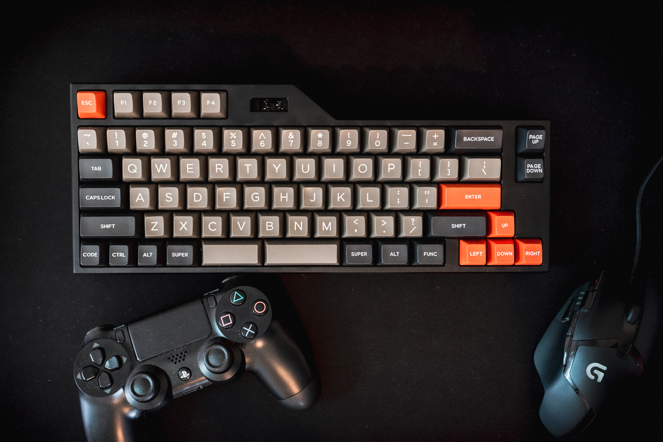
Using the Keyboard Layout Editor and working off of the “Default 60%” layout, I put an ESC key above the ~, and an inverted-T underneath the Enter.

Some new issues:
- The floating
ESCkey looks ridiculous. - Mac modifier keys are still missing.
- Spacebar still occupies the space of where I’m used to pressing the
⌘key.
So I decided to move some stuff around to where my fingers would go looking for them:
- Found the
ESCkey some functional friends:F1andF2. (I use theF2key frequently when wrestling with Excel.) - Emulated the left-side modifier command-row a la the standard Apple layout.
- Added a bunch of additional modifiers.
- Reclaimed my right
Shiftkey.
And came up with this:

This, too, had some issues—this time my concerns were mostly cosmetic (and if you don’t think aesthetics are important, you’ve found the wrong build log to read):
- The two function keys and
ESCstill seemed like afterthoughts and adrift from the herd. - The area around the
Backspacekey looked barren. Designers will tell you whitespace is nice; but this amount felt uncomfortable. - The right-hand modifier row looked cluttered and lazy; and that the modifiers didn’t stagger well with the keys above them hurt my aesthetic sensibilities, nor was I convinced I’d actually need or use them all.
- Since this is something that would live within my line of sight 8+ hours a day, I prefer to minimize the things on my desk that make me feel uncomfortable.
So, more fixes:
- Add two more function keys to visually balance the catty-cornered interted-T, and to keep the counts odd. (Groupings of odd-numbered things tend to look and feel more pleasing and grounded.)
- Simplified the right-hand modifiers so they could be offset from the keys above.
- Reclaim the real estate right above the inverted-T to add a few keys to balance the column. I frequently use
Page UpandPage Downfor one-handed lazy-scrolling, so that pair seemed like good candidates to fill the space.
In sum, I had independently derived something similar to a Leopold FC660M. (Great minds!) But as I would also come to learn, when it comes to custom keyboards, finding keycaps to match your bangin’ layout is almost as much work as designing the keyboard itself.
On Keycaps
High-quality keycaps are easy to come by; high-quality keycaps you like, well, can be a struggle.
Sites like geekhack.org and drop.com have periodic group buys and community deals on non-standard keycaps, often priced at $100s/set. But they also tend to sell out quickly.
Keycaps are their rabbit hole all unto their own.
For a moment, I considered designing or commissioning my own keycaps… but after estimating about how much time needed to model a full set of double-injection moulds for ABS plastic for over 70 different keys with 10+ different height/profile configurations (because who wants a dye-sublimated keycap anyway where the legend might wear off after a few years of use) and while I could code up a program to draw them procedurally, I would still have to find a manufacturer both willing and able to do a small run on a hobbyist budget who also had the plastic and dyes required to make high-quality and bright colorways and… (deep breath)… like I said: keycaps are their own rabbit hole all unto their own.
My advice: if you find a set you like (and can afford to be out of the money for a bit), don’t hesitate. Just buy the damn keycaps and modify your custom layout accordingly. If you change your mind on them, you can usually sell them (and be very much in the money).
This penultimate revision has one critical issue: sourcing a keycap set with a 5U spacebar and sufficient 1U modifiers seemed nearly impossible, especially in a design I liked. (1 key = 1U, so a 5U spacebar is 5 keys wide.)
Incidentally, earlier in the year I purchased a keycap set that emulated the old IBM aesthetic I liked, including the desired keyboard profile. While I had intended to use these keycaps on my 60%, I noticed that the full set also included a smaller right-Shift key, enough bottom-row 1U keys to recreate my Macintosh-style left-modifier row, and a number of spacebars to choose from. Still no 5U spacebar, but they did include a 2.25U and 2.75U that, together, would fit within the 5U space allocated for my spacebar.
A bit unconventional, yes, but after exploring what QMK firmware could do, this would prove to be quite the happy accident.
With these keycaps, I now had a viable—if not unconventional—layout.
⁂
Up until this point, I wasn’t 100% sure that I’d take the plunge on moving forward with this keyboard. But, with compatible keycaps in-hand and after days of lusting over a thing that didn’t exist, I started researching what it would take and, fairly quickly, achieved line-of-sight into what it would take to complete such a build.
Then I got to work.

One more thing…
In researching open-source keyboard firmwares, I decided on QMK as it has active contributions from other keyboard hackers and engineers, has comprehensive documentation, and supports a few cool components one might want to include in a custom build, including rotary encoders, OLEDs, sound support, and more.
With an OLED, I could avoid wiring for the Num Lock, Caps Lock, and Scroll Lock indicator lights; but also, it’s kind of a neat thing to have a keyboard with its own screen. Given the odd-shape of the layout, it felt like a nice component to help transition the 5-key function row with the rest of the keyboard’s 60% size aspirations.
If you were wondering what that dead space next to the F4 key is all about, that’s what will go there.
More later.
Case Design
If I were only interested in 3D-printing a case for my custom layout, there’s an app for that: Plate & Case Builder. It takes output from the aforementioned keyboard layout editor and pops out files that you can use to order parts from a fablab, or “print” using a 3D printer and hobbyist laser or water cutter.
But the appeal of making my own keyboard was having it be bit more… elegant. And heavier. And custom. Less hacker project and more consumer product. Also, there was aspirational OLED that the Plate & Case Builder doesn’t programmatically accommodate.
On recommendation, I used Autodesk’s Fusion360 which is free for hobbyists and (very) small businesses. Two hours of YouTube tutorials later, I felt comfortable enough with the interface to rough out some of schematics based on earlier amateurish sketches to see if they looked viable when confronted with the precision of a professional-grade industrial design tool.
My approach was to take the layout and keep the case as compact as possible while be restrained with extraneous design elements. So I took that exported .svg from the Plate & Case Builder, loaded it into Fusion360, and got to work adding material around the switch plate and planned OLED location until it looked like a product, not a project.
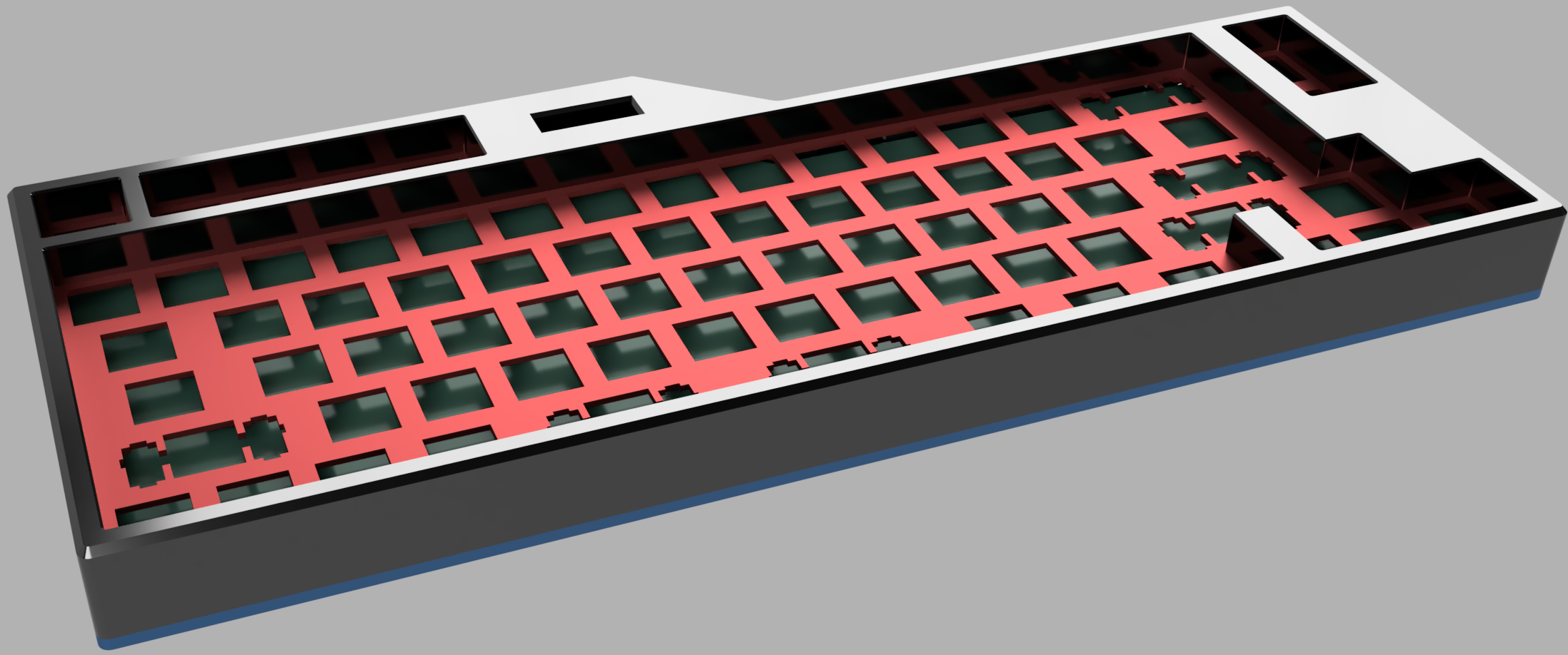
What follows is a video showing the final model before it went to production.
Note: this video isn’t a screencast that shows all of the steps that went into making the case, but rather a playback of the individual parameterized components and how they contribute to the final result.
New construction options
Going completely custom means the possibilities are, well, limited only by your time, attention, and budget. For me, I knew I was looking to build a heavy case out of a super-rigid material, but I didn’t want the daily typing experience to feel like I was rapping my fingers on a steel I-Beam all day like it does when I use a on a solid desk.
It may seem trivial, but it’s akin to dancing for hours on poured concrete vs a springy dance floor. The latter’s wood panels cushion your feet and joints which make it easier to dance, dance harder, and dance for longer. I wanted to make sure that my keyboard, while the case was solid and confident, the keys would give a little when bottomed out… which happens frequently, but especially during intense writing sessions and (if I’m honest) over intense online multiplayer video games.
Making the typing surface springy but confident took a little engineering. With a pandemic starting to spike in New York (April 2020), I knew I would have some time on my hands to figure this out. Thomas Baart makes the options fantastic clear on his keyboard mounting style cheat sheet, and I looked to emulate which seemed clearly the superior choice for my build and typing habits: the Gasket Mount.
Plate-mount vs PCB-mount vs Hand-wiring
As you may have noticed on Mr. Baart’s cheat sheet, there are options for mounting your switches. Namely, do you (or do you not) use a plate.
For me, this was an easy decision: after using the 60% GMMK keyboard which featured hot-swappable key sockets, I loved learning into what switches best suited both my typing and gaming styles, swapping out different switches to taste. To accomplish this, you need a plate.
Hot-swaps also meant that hand-wiring isn’t viable.
Like the sidebar on keycaps above, switches are a sub-category of mechanical keyboarding all unto their own. For more, go nerd out on this blog post. It’s quite good.
However cool the Gasket Mount, I didn’t love the idea of having the plate stick out from the top and bottom portions of the case like an overstuffed sandwich, nor widening the design to compensate, nor adding the complication of finding or making a custom rubber gasket that I’d have to source. Moreover, I wanted to keep the sidewall edges (the distance between the edge of the outermost key and the outer edge of the surrounding case) thin. So I opted, instead, for a top-mount design… but added some rubber washers to keep the plate and keystrokes springy.
Thinking my design unique, I have since learned that I am not at all the first to think of this and it is called (I was pleased to learn) a Burger Mount.

Zooming in on the Burger Mount itself, with some rubber washers sandwiching the switch plate:

The simple burger mount provides just enough cushioning for my fingers’ delicate sensibilities without creating an overly complicated manufacturing challenge.
Material Selection
I knew I wanted this thing to be heavy… heavy enough that it wouldn’t move even under duress.
In the realm of custom and high-end keyboards, designers seem to opt for aluminum cases with large brass inserts, which to me seems both unnecessary and expensive. (Not that any of this is inexpensive or necessary, I digress.) As Fusion360 estimated the case alone to be a 3.5 lbs aluminum block (not including the plate, switches, or PCB), I thought to go with that as it’s an easy material to manufacture, readily available, weighty, and (relatively) inexpensive.
Later (v2?), I may redesign the case to include a brass insert to give it extra heft and that bling-bling all the kids crave; but, as this is my first shot on goal, I didn’t want to worry about materials-sciencing my way into an ill-fitting scenario on an unforced error… especially since the pandemic reduced my willingness to rent time in communal machine shop where I might be able to persuade multiple materials to play nicely together.
Next time.
For this iteration, anodized aluminum with a high-precision tolerance seemed sufficient.
Design tooling
Should you opt to do your own case, I highly recommend keeping some cheap Digital Calipers handy to help translate real-world sizing from the screen and back.
Printed Circuit Board (The PCB)
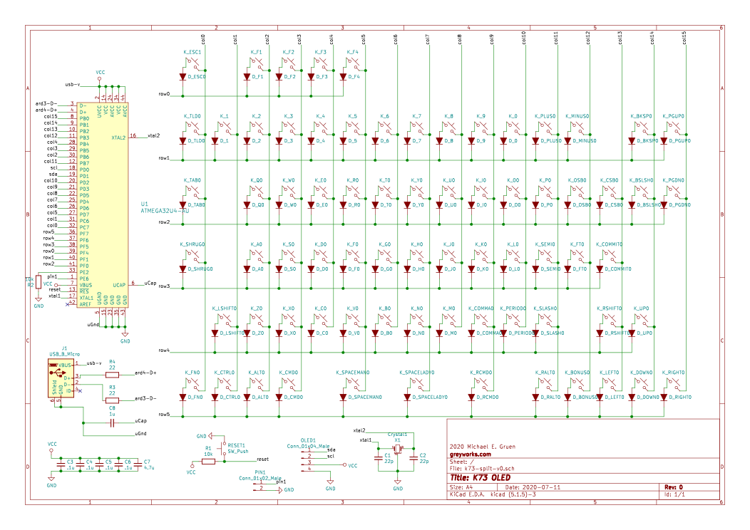
Case now designed, it was time to turn my attention to the keyboard’s central nervous system: the matrix circuit.
On direction from Ruiqi Mao’s Keyboard PCB Guide, I picked KiCad, a free, cross-platform, open-source circuit designer suite. The learning curve is a bit steep, but Ruiqi’s guide provides more than enough guidance to understand the ecosystem of complementary applications bundled within this circuit designer suite.
(To set time expectations for a basic keyboard layout, expect to know what to do and how to do it in about 5 minutes, and then allow at least 5 hours before being proud of anything you’ve done.)
First up is the schematic editor to draw the circuit diagram.
Next, I used the layout tool to turn that schematic into a printable circuit board, placing the parts and connections on the PCB, working off the same .svg from the Plate & Case Builder.
Footprint files that translate circuitry components into footprints for printing (and placing) onto silicon are available all over the Internet. Ruiqi’s guide links to some of the componentry needed, but for the hot-swappable switch plates, I had to look elsewhere.
For some of the mounting holes, I had to design my own footprints… requiring an additional 30 minutes of YouTube university with another 60 minutes faffing about KiCad.
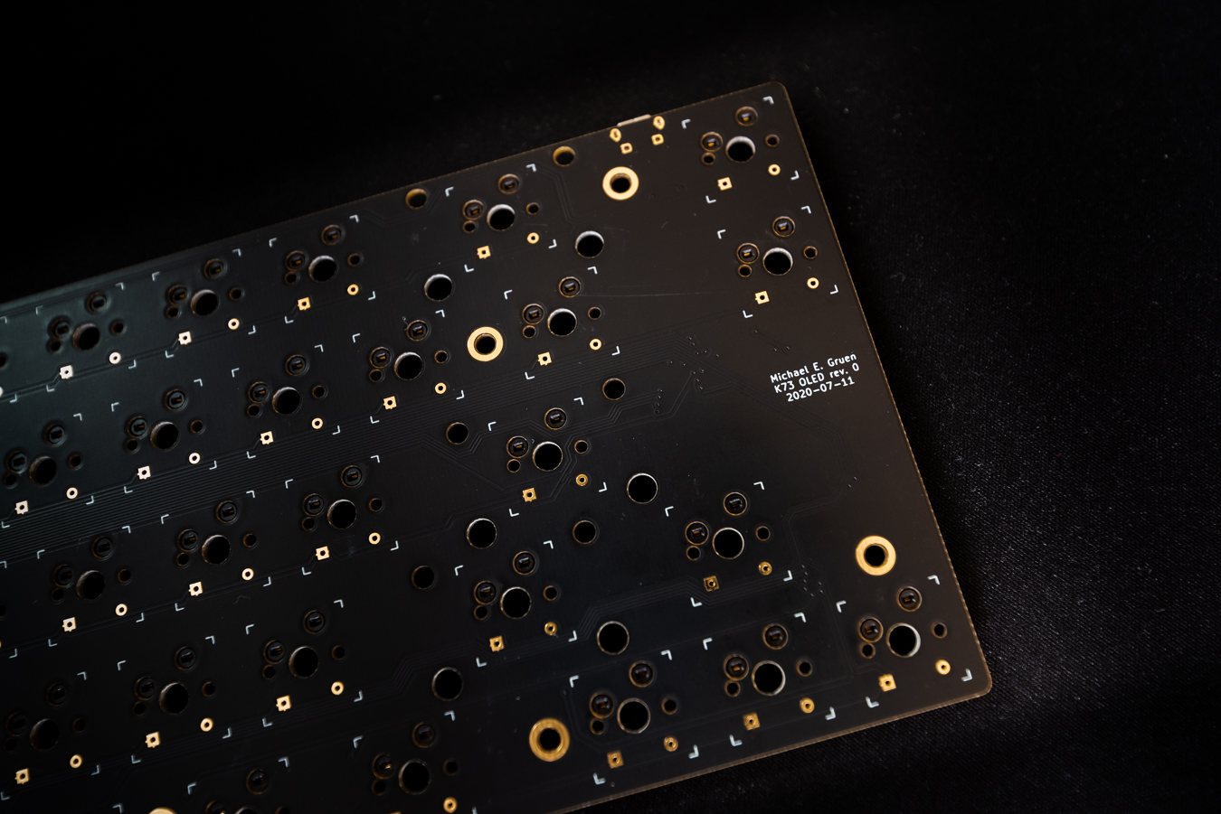
Front

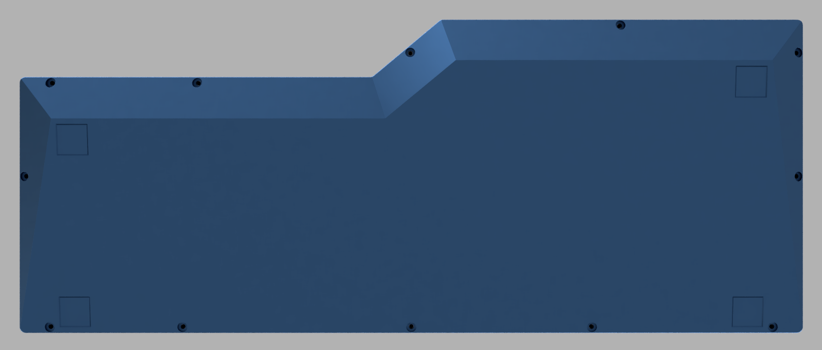
Back

3D Renders
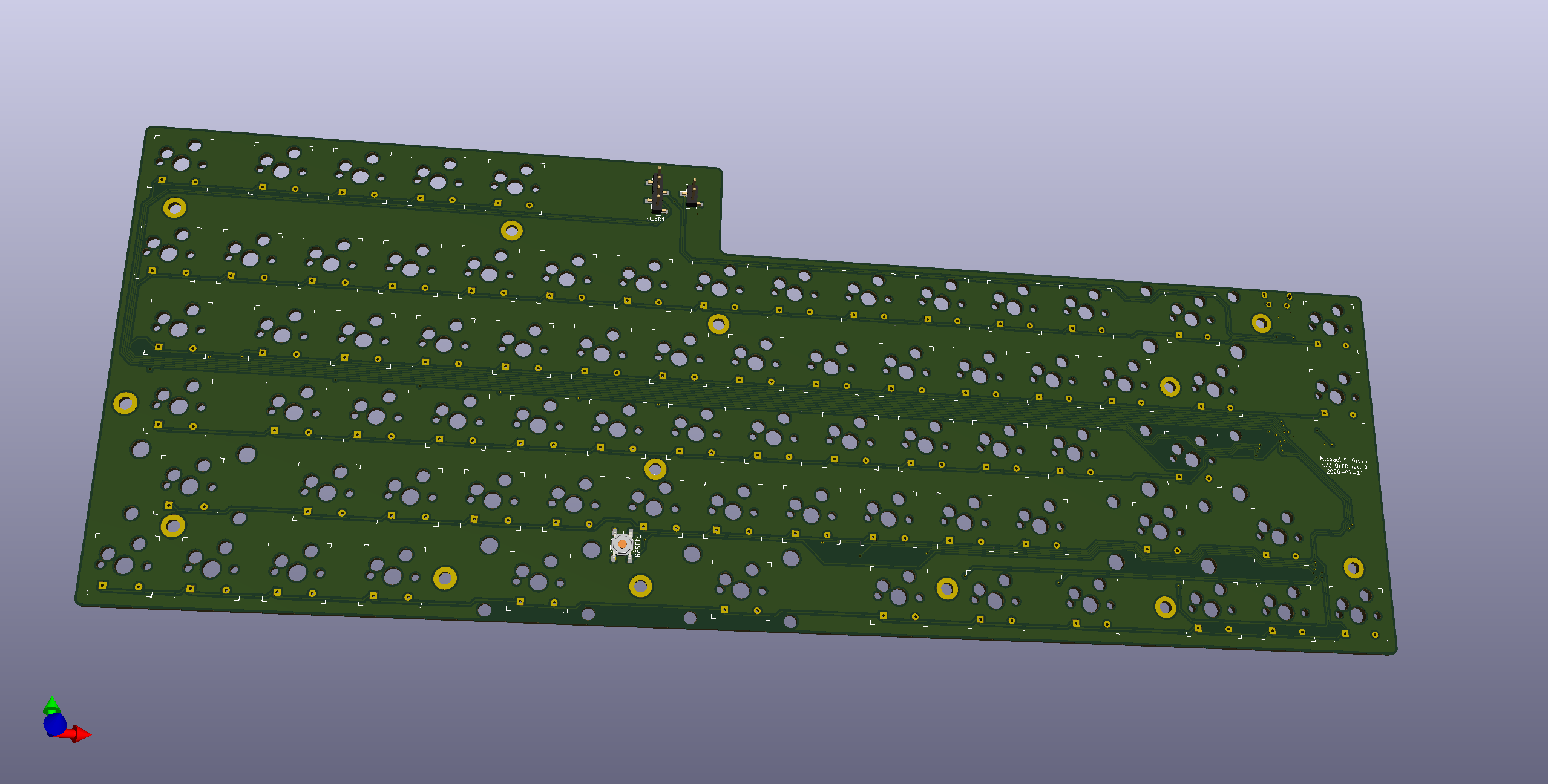
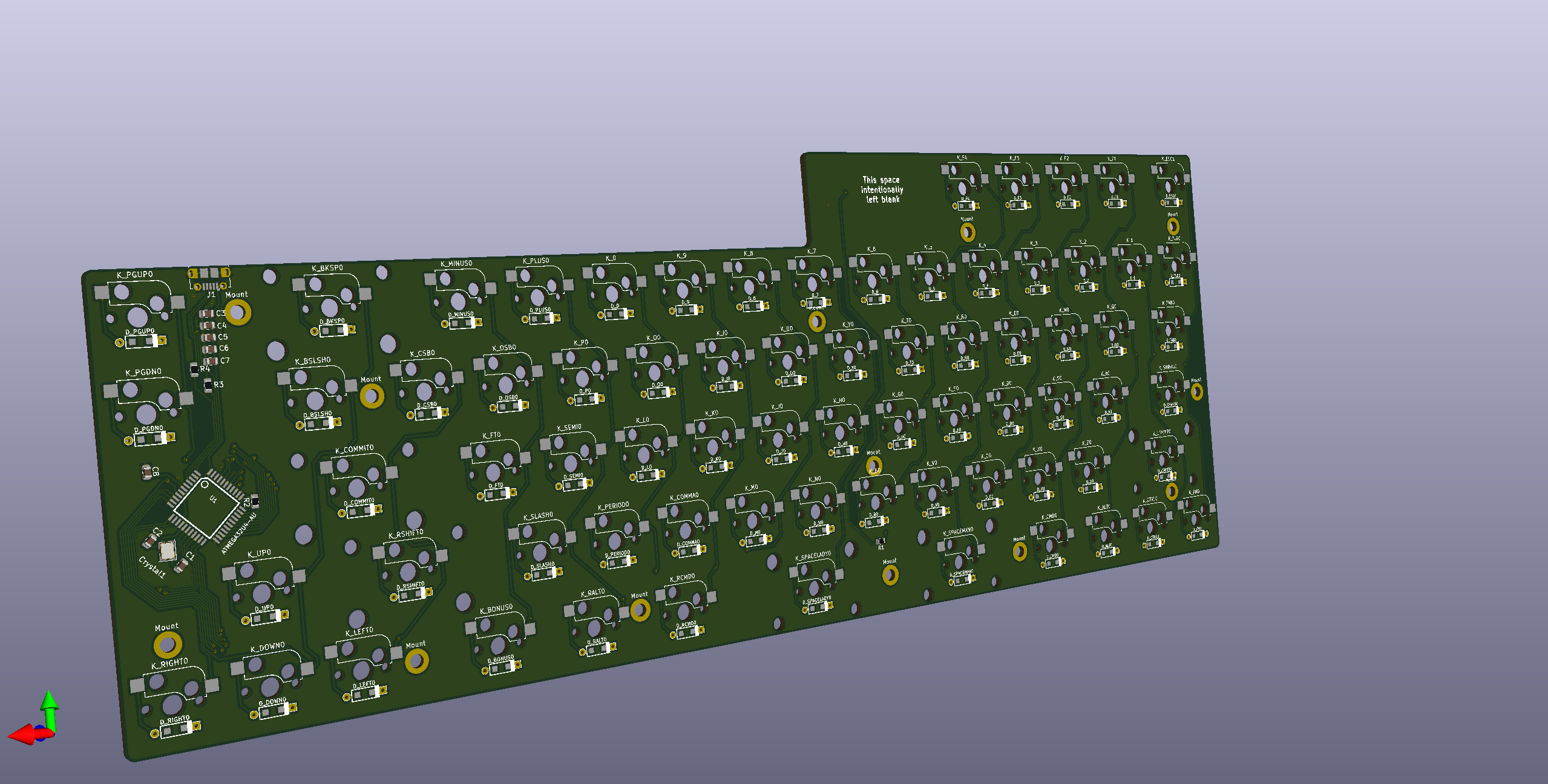
Checking for compatibility
Throughout the PCB and Case design process, I’d often switch back and forth to make sure that:
- the mounting points aligned,
- the PCB’s reset button (how you flash the firmware) was accessible,
- I was using the same units in both applications, and
- I was sizing everything to what it should be in the physical world.
Measure thrice. Manufacture once. Minimize errors.
Manufacturing
90% of this keyboard was designed in a New York City apartment amid a pandemic. My tacit goal was to manufacture locally; however, after reaching out to a few smaller local fablabs, they all informed me 100% of their capacities were allocated on building Personal Protective Equipment (PPE) for local hospitals and medical personnel and would be for the foreseeable future.
It was heartening to hear how the community rallied to support our first responders and medical personnel and I’m looking forward to revisiting these shops once life returns to some semblance of normalcy.
In the meantime, I would need to look elsewhere.
Subassemblies
To recap, at this point I’ve designed a Case (the top, bottom, and plate), a printed circuit board (PCB), and chosen my keycaps and switches. Now all that’s required is a plan on how to procure all the subassemblies needed to complete the keyboard.
Custom designs — Manufacture. Need Fabricators.
- Keyboard Case
- Keyboard Plate
- PCB
Commodity parts — Source. Find Vendors and Buy.
- PCB Components
- Case Screws, Plastic Washers, Rubber Spacers, PCB Standoffs, Rubber Feet
- Key Switches and Stabilizers
- Key Caps
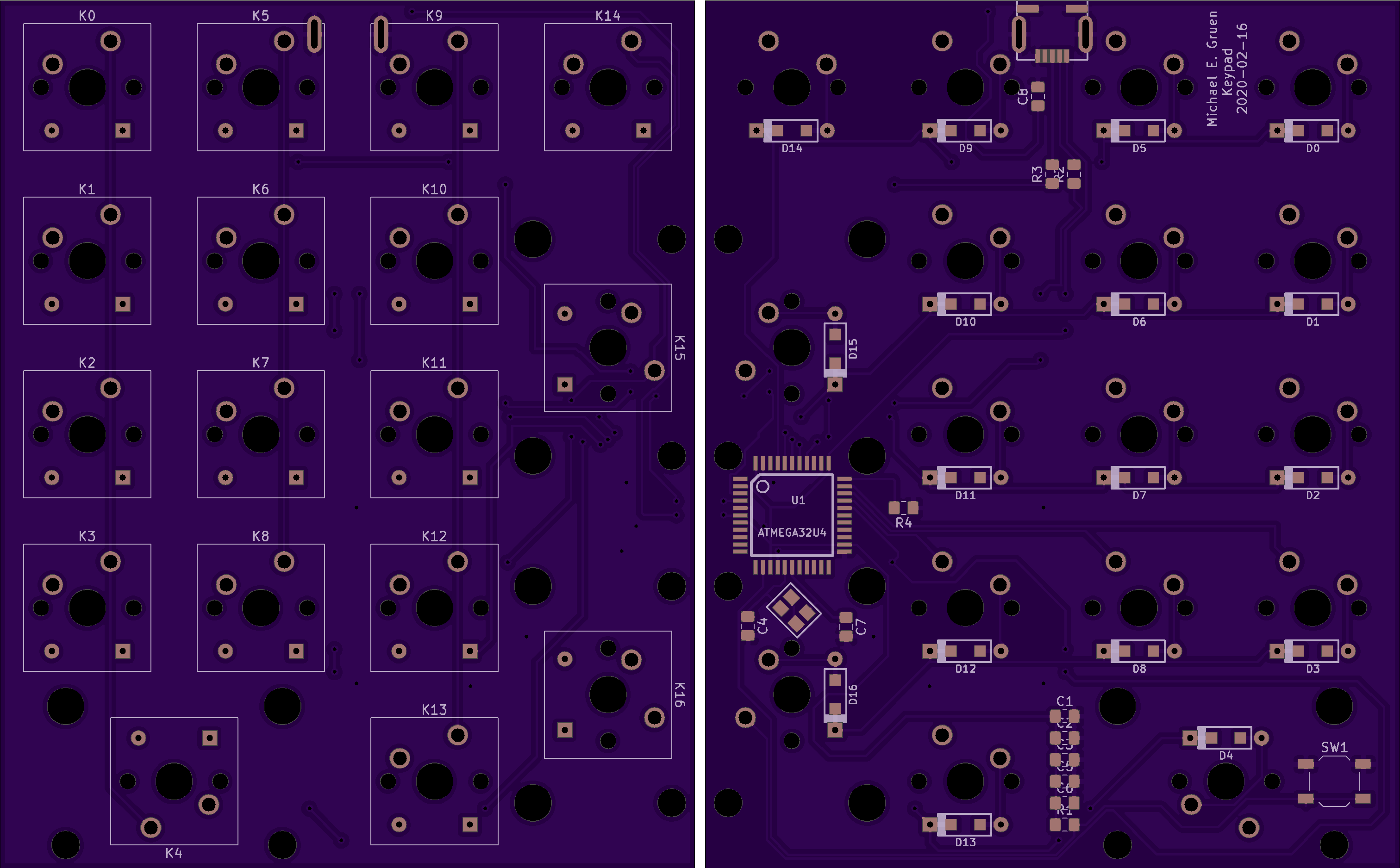
The PCB
Prior to designing the K73—and to convince myself this was a doable project—I made a number pad which, in componentry, is identical to a full-sized keyboard, but far smaller. Therefore, it’s easier to construct. Similar to the K73, I used KiCad to build a basic numpad circuit and picked OshPark with intentions to keep my sourcing US-based.
Also, I wanted to try my hand at soldering surface-mount components directly onto the PCB.
I mean, how hard could it be?
Last time I soldered anything computer-related was in college; and while the final result was functional, it was in no way pretty-pretty, and it took burning two other PCBs (and one microcontroller) to get there. (T)hese unfortunate parts had succumbed to my soldering inadequacies before I rediscovered copper wick to help undo mistakes… which is why I ordered spares!)
For an explanation of different electronic component soldering approaches, see this post.
Following that disaster, I resolved that for the full-size keyboard, I should just pay to have experts place the components. And by experts, I mean robots.
Because that’s how small surface-mount (SMT) components should be assembled. With robots. OshPark couldn’t really help here, and other US manufacturers were prohibitively expensive.
I inquired with a few PCB manufacturer/assemblers and found PCBWay to be a good and fair vendor to work with, particularly when it came to helping me source commodity components. They also worked with me on parts they couldn’t source, like these Kailh Hotswap Sockets. (PCBWay’s facility, by the way, is bananas.)
The process is fairly straightforward: export from KiCad, upload a mess of files (called “gerbers”) to manufacturer, clarify any nits or ambiguities with your account manager, and trust them with your credit card. Where they had questions or got stuck with my terrible instructions, they’ll e-mailed me until they get un-stuck.
About a month later, a fully-assembled PCB arrived with my name on it.
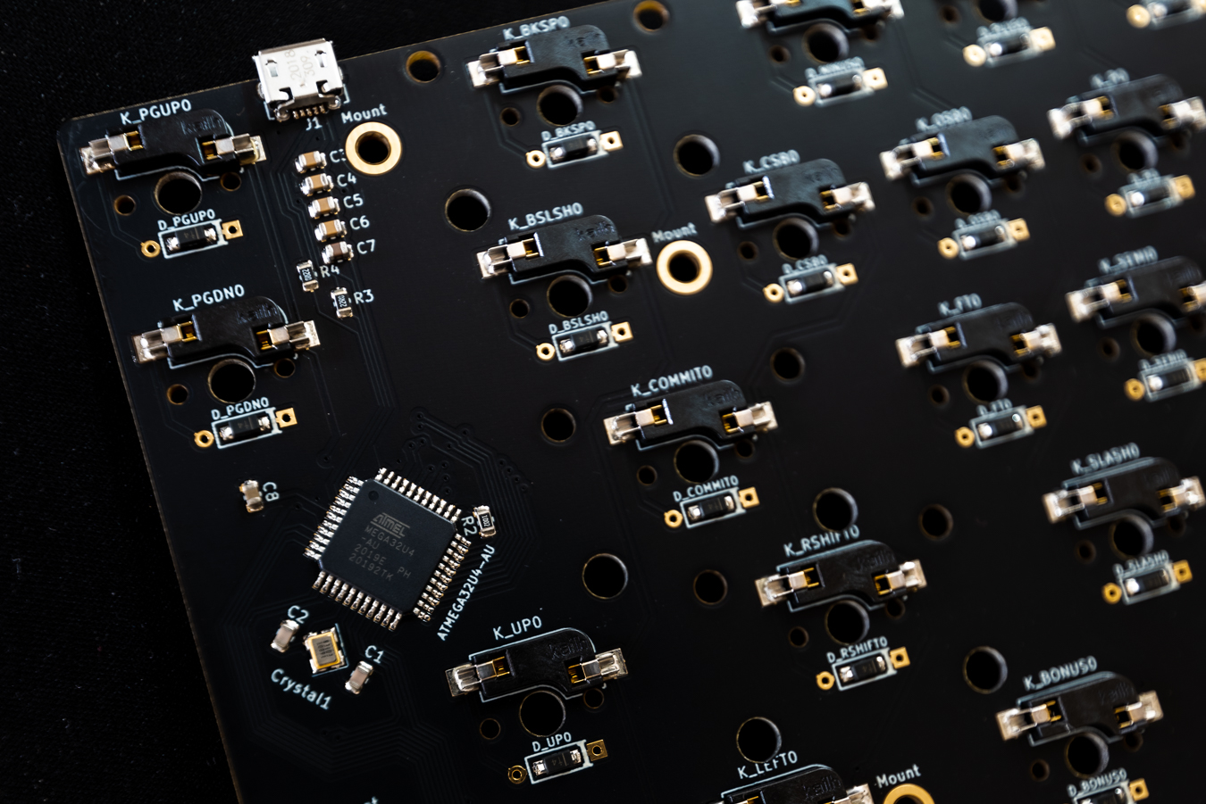
Well, 5 of them actually. I didn’t understand why at the time, but after watching the above video about their facility tour, the minimum order quantity (MOQ) made a lot more sense. And given my history trying to undo mistakes amid a pandemic, spares made sense.
This was fairly painless. The case, on the other hand…
The Case
I had trouble finding a US-based manufacturer that:
- as mentioned earlier, wasn’t 100% focused on churning out literal tons of pandemic-grade PPE, or
- didn’t cater to the US-based aerospace and large industrial design parks with absolutely ludicrous small-batch costs and lead times.
So, alibaba.com it was.
Finding and working with a small-batch manufacturer on Alibaba
While Chinese firms dominate the marketplace, manufacturers from nearly every country have a storefront on Alibaba. As a marketplace, it is truly amazing and a wonder of the modern economy.
I searched for rapid prototyping aluminum machining and found two potential partners (both in mainland China) who could write well enough in English, and offered both manufacturing and shipping services at—air quote—”reasonable” rates. Negotiating between the two, I settled on a fair price, sent over the
.stepfiles exported from Fusion360, some plan renderings that described the screw hole threading requirements and material finishes, and punched my American Express into Alibaba’s international pay service.A few weeks later, my case arrived.
Fantastic.
My Alibaba-sourced manufacturer was responsive and communicated every step of the way, sending photos and videos following each stage of the process and checking for approval. My representative also highlighted potential issues with my design files that could (and did) lead to minor cosmetic issues.
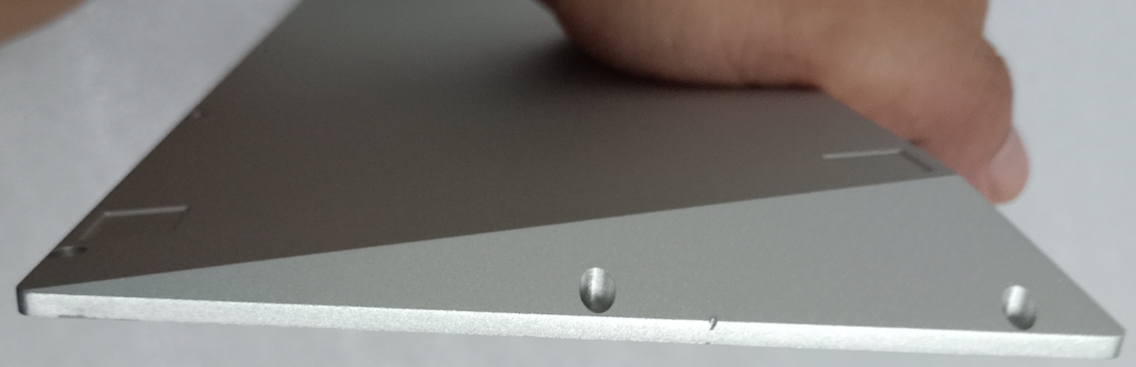
For instance, I had neglected to think through think at all about how the anodization process works, prompting a subcontractor to “get ‘er done” in the absence of any cosmetic direction or proper manufacturing design. (Not a big deal, but worth mentioning for future projects.)
To make sure I wasn’t getting the run-around, I reviewed the photos showing said minor cosmetic issues with some folks who have far greater experience working with offshore manufacturers. They were all impressed not only with the communication and candor, but also the quality of the functional prototype and willingness to correct minor mistakes, especially given the negotiated price.
Update: My vendor asked that anyone interested in working with them e-mail Tony directly.
To see more of their work, check out u-created.com
Assembly
Once the final DHL box arrived, I was ready for final assembly.
The PCB to Plate Connection
As I chose to go with a switch-swappable PCBs combined with a floating burger-mount design meant that I needed to figure out how to create the PCB and plate subassembly without relying on the switches to do the work.
Normally, keyboard builders solder their switches directly to the PCB as part of the build. The two PCB solder points and the switch’s two plate pressure clips, across all of the key switches on the keyboard, provide more than enough connection points to hold it all together.
But I didn’t want to do that, because (as has been endemic here) I didn’t want to make a switch decisions at design time and wanted the hot-swappable… which means zero soldering on the key switches.
Additionally, I was nervous about building standoffs directly onto the plate or PCB. From a manufacturing accuracy and cost perspective, adding standoffs and/or threading to the plate would add complexity and potential for alignment/manufacturing errors. Again, pandemic-era errors are doubly painful as there’s no good way to address the problem other than order a new component. Further, loading the PCB with tension from a high-torque screw seemed like a recipe for silicon structural failure and a lost PCB.
Rather than take that risk, I aligned the design to match locally-available parts that had a day or two lead time rather than the month-long lead time waiting for replacement PCBs from China.
As McMaster-Carr makes ordering precision fasteners to my door incredibly easy, it felt like the right decision if not complete indulgence. Their parts are super high-quality, but super expensive.
Now, had I done any homework at all I would have learned that there are catalogs of standoffs engineered for exactly the purpose of mounting PCBs at a fixed distance from metal surfaces. Ignoring all of that, here’s the solution I came up with using a threaded standoff flanked with three times as many parts (and therefore about three times as expensive) as I should’ve needed.
Nonetheless, it worked like a charm:

Parts List
Here are all the parts (with my chosen vendors) should you want to play along at home:
- Custom PCB (PCBWay)
- with Kailh hot-swappable sockets (KBDfans)
- commodity components sourced by PCBWay (with small markup)
- Custom aluminum case (silver anodized), ~6% rake (u-created.com)
- M2 low-profile screws (McMaster-Carr)
- Custom steel plate (black powder-coat) (u-created.com)
- burger mounted to the case top with rubber washers and M2 screws (McMaster-Carr)
- PCB mounted to plate with some spacers and plastic washers and M2 screws (plate side are flat heads) (DigiKey)
- Gateron Silent Browns tactile switches (for now) (FlashQuark)
- and pre-lubed plate-mount stabilizers (KBDfans)
- Generic $10 OLED (amazon.com)
- Domikey SA 1980S (drop.com)
- 3M rubber feet (DigiKey)
If you want to see a master keyboard assembler at work, I recommend checking out Taeha Types. Please imagine in your mind’s eye that my workspace and approach is just as complete and competent, and it was with that grace, poise, and sense of calm that I assembled my own keyboard… which is of course a total lie, but I appreciate you indulging me.
Recall my plan had one major flaw: I had neglected to think through how I was going to mount the OLED prior to ordering.
The OLED
Before this write up, I submitted an image of the final build to the Mechanical Keyboard subreddit and received the following question:
I’m curious, you made a fully custom machined case, plate, and hot-swap PCB then just taped the OLED in place? Looks beautiful, just confused on that lol
To which I responded:
Yes, that’s exactly right.
After designing the PCB, plate, and case to play well together, I just didn’t have the patience to figure out how to best mount the OLED onto the PCB and have it sit at the right height. Knowing the lead time would be a few months, I just left myself a modicum of space to work with and hoped for the best.
That was not smart. Took me about 3 hours to desolder the OLED pins, figure out how much room I needed for the wires (and where they would go when the case was fully assembled) and will it into place.
Further, the OLED’s PCB wasn’t a perfect rectangle so I shimmed it with some electrical tape.
Next time, I will do it right and just solder it directly to the PCB with a plastic spacer/mount to fine-tune its placement.
Also, what I didn’t mention there was that I was designing this entire build without any prototyping capabilities, and I wasn’t at all confident in my ability to get the engineering marriage between the PCB and the Case aligned correctly on the first time. Other than an inexpensive soldering iron (that I can’t recommend to anyone) and some sandpaper, I thought it less risky to kludge it together than attempt to do it right and get it completely wrong.
So with a healthy amount of electrical tape, insulated wire, and swearing, that’s what I did.
YOLO.
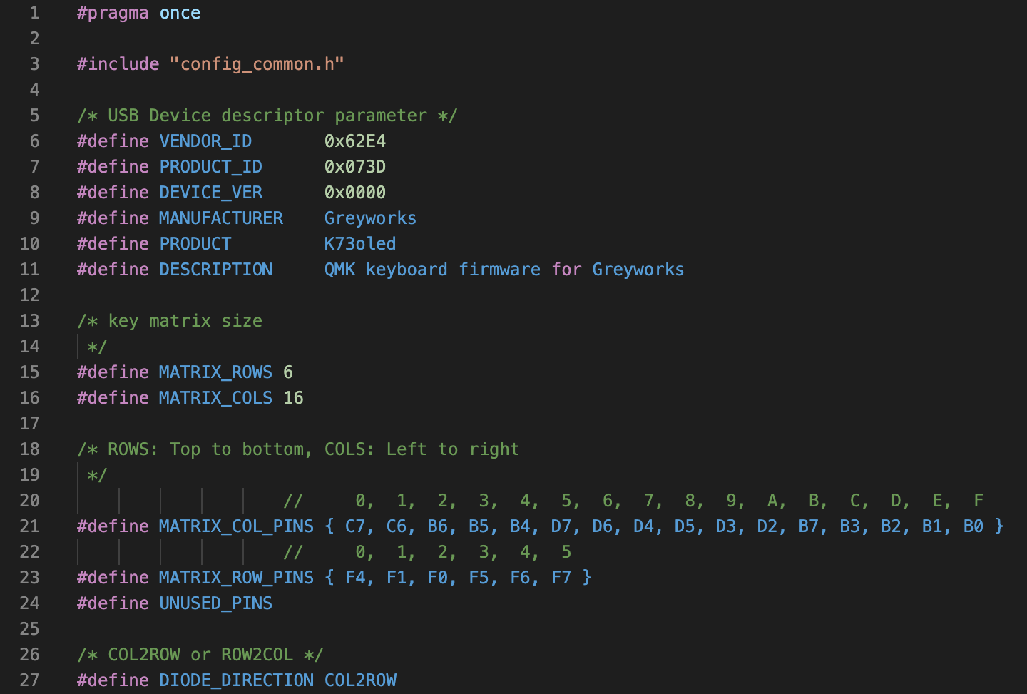
Firmware
With the keyboard fully assembled, now is perhaps the worst time to write the firmware to check and see if all that painstaking work of laying out the PCB, components, and assembly would properly yield a functioning peripheral.
While I was confident that the QMK Firmware would work, I wasn’t 100% sure that I hadn’t made in a critical error within my wiring or layout. Either way, I was hopeful, and sat down to write the keymap file which instructs the firmware to understand the matrix circuit that I’ve wired into the microcontroller, and provide instructions to the OLED on how to behave.
I hadn’t written any C-lang in over a decade, so this was a trip down malloc lane.
Custom K73 Features
A few special features of K73, enabled by the QMK firmware, the split spacebar, and the OLED:
- The left spacebar is a spacebar… and an extra modifier
- QMK has a built-in function that enables a key tap and a key hold to function differently; say, be a spacebar when pressed normally, and becomes a modifier when held.
- Holding
spaceand tapping a number key emulates the function row. (e.g.space + 5→F5) - Holding
spaceturnsWASDinto arrow keys. - And some others.
- Layout Switching
- Supports QWERTY and DVORAK at the hardware level.
- Supports Windows Modifier Row and Macintosh Modifier Row by cycling through different keyboard modes.
- Layout Modes are displayed on the OLED.
- Holding the
CODEkey and pressingFUNCcycles through modes.
- OLED-supported modifiers
- Show which keys are being pressed.
- Unobtrusive, but obvious,
CAPS LOCK,NUM LOCK, andSCROLL LOCKindicators.
- … and more! (Once I get around to it.)
Building… Construction Complete
Once I found my missing semicolons, the firmware was ready to build.
It took me about 10 minutes to understand how QMK’s make files work (8 minutes of which was relearning how a makefile works), and another 5 minutes to compile (running QMK’s build routines through docker on a MacBook Air adds a bit of a delay).
Compiled, I loaded the binary onto the microcontroller using QMK’s firmware utility…
…and this is the moment—the moment where K73 should come into being. Months of effort, hundreds of parts, dozens of lines of source code, and not an insignificant amount of capital all coming together in a pile of aluminum and silicon designed to my exact specification. The anticipation of whether or not this mechanical keyboard neophyte could pull it off had reached the critical moment: would my computer recognize its purpose of being and treat my creation as a valid peripheral? Or was there a fatal flaw, a design error that would relegate my efforts dead-on-arrival to forever live on my shelf as abstract art, a visual reminder of failure in hubris…
…and it loaded in under three seconds.
And it worked.
And it felt entirely uneventful.
⁂
Hold on, though… maybe something went wrong that I didn’t notice at first. I should run through some tests.
- Test all the keys. This Keyboard Checker makes sure all keys register with the operating system. Professional keyboard assemblers advise you to test your PCB before you build the rest of your keyboard. I disregarded their advice and trusted the quality control team over at PCBWay to have done this for me correctly. I pressed all the keys and all lights turned green. PCBWay didn’t fail me. All key work. Check!
- Test the firmware and matrix for N-Key Rollover support to increase typing accuracy and gaming input clarity. Success!
- Tested my typing speed and see if this was all worth it. ([I clock in around 95 words-per-minute… which is about average for me. So, no firmware or latency issue.)
So, no. No issues whatsoever. It worked perfectly.
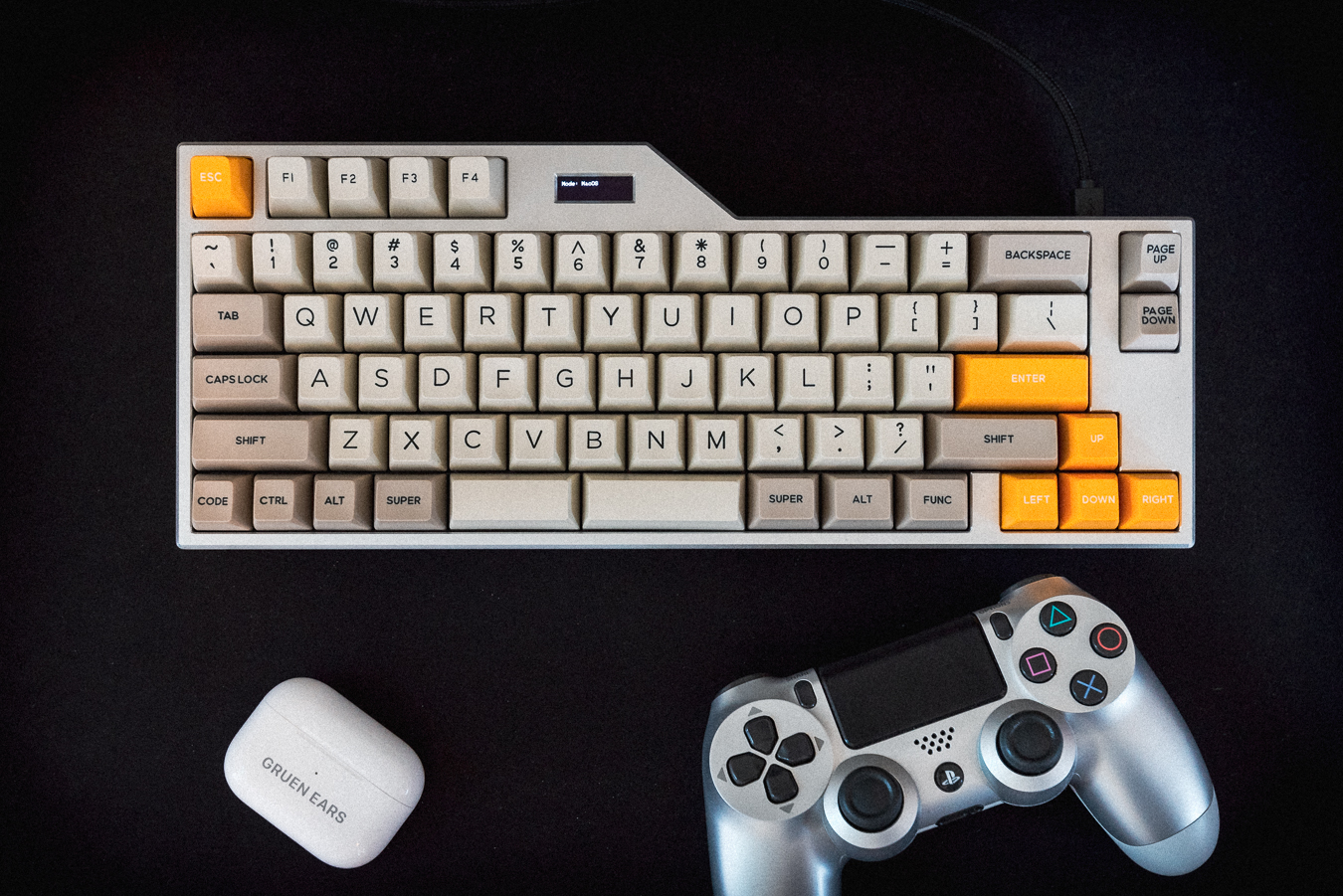
Done
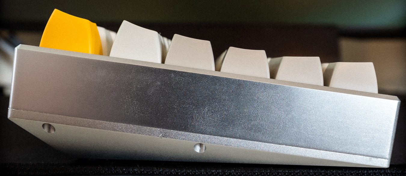
Here it is… a functional workhorse with 73 keys (with some other common desk inhabitants for scale):
Epilogue
As of writing (late November 2020), I’ve used the K73v1 every day for about 3 months now. Here’s what I’ve noticed:
- From day one, the keyboard just felt right. The key switches are super-fast and tactile and the keys are exactly where I want them to be.
- The whitespace around the
ESCkey, function row,BACKSPACE, and arrow keys make them easy for my fingers to locate without my eyes leaving the screen. - The angle of the keyboard, with the keycap profiles, means I’m never over-extending my hand to reach for a key far away from the home row.
- My error rate has fallen significantly. Like the IBM keyboards of yore, the keycap tops have a smaller area than the chiclet keyboards common to the Apple lineup. Accidental (fat-finger) key presses are less common.
- The split spacebar is faster than the full-length spacebar. For event faster double-spacing, I can double-tap the spacebar with both thumbs. (n.b. For those born before 1980, despite your typing tutor’s insistence, only one space belongs after a period as modern computers know how to kern properly.)
- I do miss some of the media keys from the Apple Wireless Keyboard (which was my daily driver prior to buying the
60%mechanical keyboard). Will have to think through a good solution to that which doesn’t involve restoring the function row (because, in the case of Apple, they continually change the function row’s purpose if not removing it all together in favor of this ridiculous second screen touchbar that requires looking at what you’re doing as critical functions, like volume, are subject to move on you and seemingly without reason). - Most importantly, typing on the
K73has become a joy as if every commute felt like a Sunday drive.
They say as you spend 30% of your life in bed, you should invest in a good mattress. With over 40% of my day spent in front of a computer, why was I typing on the functional equivalent of a futon?
I should have done this years ago.
Photos
I’ll give the K73v1 the photoshoot it deserves once I can figure out a better lighting situation. The gallery will likely end up on Exposure where my photography generally lives. The images on this page were taken in haste late one afternoon.
Clearly I need to up my product photography game.
Budget
Setting out, I had no strict parameters on what I thought an appropriate budget would be. I’ve worked in technology long enough that it always costs twice as much and takes twice as long. For K73, that axiom continued to prove true.
Not including time spent, I estimate the total build cost more than a Chromebook but less than a MacBook… but I suspect it will outlive several generations of both.
Want one?
I’m considering doing a small run of this keyboard, with a few flexible modifier row options to accommodate the PC users among us (myself included), and maybe with a PCB meant for soldered switches, with all of the minor nits expressed above addressed in v2.
If you’re interested, e-mail me for details.
FAQ
In advance of this write up, I’ve already had to answer a few questions about it as I showed my work to friends and random interested strangers.
1. Where are your LEDs?
The intent was to build a workhorse keyboard for day-to-day work purposes. Maybe I’ll include addressable LEDs or ground effects in the next build.
Don’t count on it, though.
2. What’s your angle?
It’s 6° itself and about ~8° when you include the SA profile. A keyboard rest (currently using the GMMK wooden rest for compact keyboards) is helpful.
3. Why Micro-USB and not USB-C?
Backwards compatibility. USB2.0 is still alive and well, the cables are cheaper, the parts more available, and I didn’t feel like figuring out the USB-C female pinout requirements at the time of design as it’s a bit more involved than its previous generation counterparts.
To be anachronistic, I nearly went for USB B-type connector.

4. What mistakes did you make? What are you going to change for next time?
- The mount hole on the left shift interferes with the stabilizer. I need to flip the stabilizer layout or (re)move that mount point altogether.
- I have about twice as many screws to attach the top and bottom parts of the case than I need. Next iteration, I plan on removing the side screws for better aesthetics as, strength-wise, it’s already over-engineered.
- I should have manufactured the PCB with press-fit standoffs to avoid the headache of working with 4 small, delicate parts when 1 would have sufficed. (This was discussed above.)
- I need to learn how the anodization process work so I can avoid some of the scarring that comes out of that process. Further, learn what else one can do with the anodization process, color-wise.
- Next time I will buy pre-lubed switches. Lubing 73 switches was painstaking work, even with the proper key opening tools, brushes, and lube. (Yes, lubing your switches—and stabilizers—is worth the effort)
- If you want to use costar stabilizers, don’t try to plate mount them with standard Cherry MX stabilizer patterns in the plate itself. It won’t work, and you’re going to have a bad time.
- I didn’t need 5 rubber feet on the bottom. On non-flat surfaces, it lead to some wobbling… which is exactly what you don’t want.
- Could’ve thought more about the media keys, although I’m thinking to port that functionality for a secondary peripheral…
5. What does it weigh?
1802 grams (~4 lbs).
6. What’s with the Pin-1 on the PCB?
First of all, good eye.
Well, after using every other pin available on the microcontroller, I didn’t feel like wasting it. Maybe I’d run an LED to it later. Either way, wanted easy access to it for later.
One more thing…
It also comes in black.